Error message

Warning: file_get_contents(https://ipinfo.io/18.97.9.175/country): failed to open stream: HTTP request failed! HTTP/1.0 429 Too Many Requests in include_once() (line 654 of /home/wireterminalstre/public_html/sites/default/settings.php).

Pull test standards and methods

Background
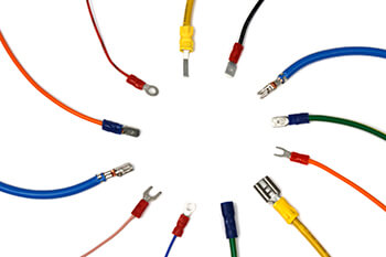
Variety of crimped wire terminalsThe quality of a crimp joint depends on the mechanical strength of the joint as well as its electrical conductivity. If results from pull force tests are within an allowed range, it assures that the proper crimp force has been applied during the crimping process.

This is crucial as enough force must be applied to break down the layer of non-conductive oxides that may build up on the stripped conductor and the plating on the inside of the terminal. This is necessary to provide a good metal-to-metal contact. If this does not occur, electrical resistance can increase.

Overcrimping a crimp termination will reduce the circular area of the conductor and thereby increase electrical resistance.

Crimp joint testing (commonly known as "pull testing") ensures the integrity of the final product but, more importantly, it ensures the effectiveness of the crimping tool itself since it can be calibrated according to test results. Calibration is best carried out in response to Statistical Process Control (SPC) analysis which can be gathered from data obtained by pull testers.

Standards and methods

There are many standards to adhere to and each manufacturer or user might have different requirements to fulfil. But one thing in common is that international and industry standards all prescribe procedures for testing the tensile strength of wire terminals in a repeatable manner.

It is essential that there is no jerking or sudden application of force. This is the reason why standards state that there should be a 'constant rate of pull' and most define a pull rate at which tests should be performed. The only practical way to achieve repeatability for pull force tests is to set a speed by using a motorised pull tester such as the WTST range of testers.

Although standards define a minimum acceptance-value for the pull force according to the wire diameter and AWG conductor size, it is of greater importance to the manufacturer and user to know that joints can definitely sustain higher loads. So an increasing axial force is applied to the connection until either the terminal and wire separate or the wire breaks.

Pull and Break

Directly pulling the wire joint until destruction at a constant rate (typically 25 to 50 mm/min) is the most commonly adopted test method and is known as 'Pull and Break'. It is performed by using a motorised pull tester in which the peak force to separate the terminal from the wire is measured. This value is then compared to the table of minimum pull forces outlined in the standard in order to determine a pass or fail of the connection.

Other test methods call for more in-depth procedures: 

When carrying out a pull test most companies do not remove the insulation sleeve around the crimp. However, the IPC/WHMA, UL, USCAR and VW standards specifically require that the insulation support is rendered mechanically ineffective by opening it up. Certain other standards (e.g. VW) provide a higher pull force value if the insulation support is left in place around the crimp.

  • Pull and Return
    A non-destructive test whereby the terminal is pulled to a specified force and then the force is removed.
  • Pull and Hold
    A non-destructive test whereby the terminal is pulled to a specified force and held for a specified period of time. The force is then decreased to zero.
  • Pull, Hold and Break
    A destructive test whereby the terminal is pulled to a specified force and held for a specified period of time. It is then pulled further until either the terminal and wire separate or the wire breaks.

Electrical (general)

Section 19.7.2 defines the mechanical test method - Pull Force (Tensile) for crimps and soldered connections stranded wire.
Pull rate 25 mm/min.
This standard is recognised as the primary reference for wire harness manufacturers.
486-A, 486-B :  This safety standard applies to single-polarity connectors for use with all alloys of copper or aluminium, or copper-clad aluminium connectors. Section 9.3.4relates to the pull-out test of wire connectors and soldering lugs.
486-C :             This safety standard relates to splicing wire connectors. Section 9.3.4 covers the 'pull out' test method. Section 9.6 covers the 'secureness of insulation'.
This test method establishes the requirements for a standardized method of evaluating the quality of crimped-type electrical connections to solid or stranded conductors. It applies to 16-gauge and smaller diameter copper wire, coated or uncoated. 
Pull rate 25 mm/min
Specifies requirements for metallic, non-metallic and composite cable ties and their associated fixing devices used for the management and support of wiring systems in electrical installations.
Includes a 'Pull and Hold' method for testing the loop tensile strength of cable ties (both metallic and non-metallic types).
Describes methods for testing the tensile strength and insertion/withdrawal of flat-quick connectors. It covers the connector type where the male tab has a hole or dimple detent and is fitted to a female connector.
This standard establishes a test method to determine the axial tensile load that can be applied to a mated pair of connectors. It covers the holding effect of a connector cable clamp without causing any detrimental effects upon the cable or connector when subjected to inadvertent axial tensile loads. 
A 'Pull and Hold' test is prescribed where the pull force is applied to the connector at a loading-rate ( 89 newtons per minute) up to a specified level and then held for 1 hour, whilst electrical continuity at 100 mA is measured.

Automotive

USCAR (US Council for Automotive Research) standard 21 - includes pull testing for validation of solderless crimped connections used with stranded automotive copper wire.
Pull rate 50 - 250mm/min (100 mm/min preferred).
This automotive company standard relates to solderless crimp connectors using crimp barrels and conductors made of flexible copper and applies only to single cable crimps. Sections 5.2.3 and 5.5.1 covers the 'conductor pull-out strength' test method.
This automative company standard is based on the template LV214 drawn up by Audi, BMW, Daimler, Porsche and VW. It relates to solderless crimp connectors using crimp barrels and conductors made of flexible copper. Section PG10 covers the 'conductor pull-out strength' test method.

Aerospace

Provides test requirements for the crimping of insulated and non-insulated terminals and splices to general purpose electrical cables, or equipment wires for aircraft, with conductors of copper, copper alloy, aluminium or aluminium alloy.
Pull rate 25 - 50 mm/min
Describes the design requirements and tests for the crimping of insulated and non-insulated terminations to general purpose cables, with conductors of copper, copper alloy, aluminium or aluminium alloy.
This standard sets out requirements for measuring the integrity of crimped connections for interconnecting cable and harness assemblies. It is applicable to NASA programs involving flight hardware and mission-critical ground support equipment. 
Pull rate 1"/min
- 408 Elements of electrical and optical connection: Describes a procedure for measuring the mating and unmating forces for elements of connection.
- 412 Elements of electrical and optical connection: Describes a procedure for measuring the contact insertion and extraction forces.
- 417 Elements of electrical and optical connection: Defines a method of determining the tensile strength of crimped connections.
This standard for aircraft wiring specifies a method of determining the forces required to insert and extract the contact pin into and out of the terminal socket of the signal contact.
Defines a method for testing the loop tensile strength of cable ties for use in aerospace applications.

Military

SAE (Society for Automotive Engineers) standard AS7928 - applicable to military applications. Includes pull testing of insulated and uninsulated crimp-style copper terminal lugs and conductor splices for stranded conductors.
Pull rate 1"/min. 
Def Stan 59-71 specifies the mechanical and electrical performance requirements for crimped electrical connections onto copper conductors for use in military equipment and systems. It details the crimp evaluation tests which shall be met by a 'Capability Approved' terminal, splice or connector contact when crimped to a copper conductor.
Pull rate 25 - 50 mm/min
This US military standard contains method 211. It covers a procedure for tensile testing wire-lead terminals, flexible-flat-strip or tab-lead terminals, and rigid-type terminals which are threaded or have other arrangements for attaching conductors.